


Weston Photronic Relay Model 607 US manufacture, 1932
Having developed the Photronic cell, Weston were fully committed from 1932 onward to implementing it not just in photographic exposure meters, but in the widest possible industrial environment. Alongside workplace light assessment meters such as the model 703, they realised that the cell could form the essential building block for a multitude of other tasks, such as turning on lighting when ambient light levels dropped.
Their primary objective lay in making electrical engineers, students and systems designers aware of the potential, for automation in particular, of a wide range of tasks that may have previously been laborious. Enter the 607 Photoronic Relay board: This is a simple linking together of three key Weston instruments: The 594 Photronic Cell, the model 634 Miniature Relay and a coil-actuated power relay. They are mounted on a demonstration board with the connection paths clearly marked out. The wiring is on the underneath. The miniature and power relays are enlivened from a 4.5v DC supply and the Photronic cell can be plugged into either of two sets of sockets, allowing the triggering of the miniature relay either from the cell's current increase in bright light, or the converse in low light or darkness. All manner of auxiliary devices, systems and circuits can be connected to the switching terminals of the power relay, so allowing them to be governed by changes in the light falling on the cell.
I am indebted to Jack and Claire Billington in the USA who made it possible for me to get this item across the pond. With a serial number of #302, it is clear that this unit was only made in small numbers and I doubt whether any others at all exist on this side of the Atlantic.

Weston supported the 607 experimenting board with instructional documentation. This is an extract from a booklet of Interesting Experiments, a copy of which can be found on my site HERE. This particular circuit shows clearly the three components of the relay board in line: The Photronic Cell, Miniature Relay and Power Relay. Connected to the output terminals is a simple lighting circuit with a manual over-ride switch, automatically turning on the night light when daylight fails.

The 594 Photronic cell is shown here mounted on one of the two available sets of pins, and facing outwards to capture light. The cell can be used off the board as part of a remote sensing device.
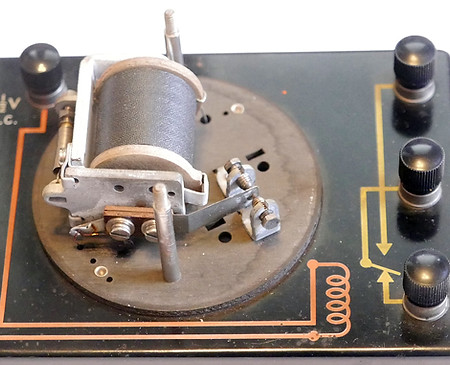
The cover to the type D6890 Power Coil Relay has been removed to reveal the actuator coil, armature and switching relay.